Table of Contents
Components
This stage involves the following new components.
Setting the Base
After taking the Arduino out of the box the first thing to do is to connect it to the breadboard using wires.
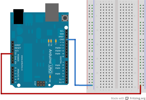
First, we need to wire up the breadboard's power rails that go up each side. The power rails are designed to give easy access to 0V (also known as GND) and 5V.
- Using a blue or black wire connect one of the GND pins on the Arduino to the blue rail on the left of the breadboard.
- Using a red wire connect 5V on the Arduino to the red rail on the right hand side on the breadboard
Once you've done this the breadboard and Arduino should look like this.
Let there be light
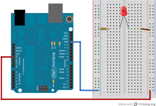
Now we will power an LED
- Place a 180 ohm resistor (colour code = brown, gray, brown, gold) from the GND power rail to a line on the central part of the breadboard
- Then place an LED from the 5V power rail to the the same line on the central part of the breadboard.
(Tip: If you want to zoom in on any of these diagrams, just click on them!)
Remember: With resistors it doesn't matter which way round you put then, but with LEDs it does. See this page for more information.
- Now you plug the Arduino into your computer with the USB cable, it should start providing power to the breadboard, lighting up the LED. If the LED doesn't light check that it's the right way round.
Blinkenlights
Having an LED lit is cool, but the Arduino is so much more than just a power source! Let's control the LEDs, first by blinking it on and off once per second.
- Disconnect the USB cable from your Computer. This removes power so prevents bad things happening whilst you change the connections.
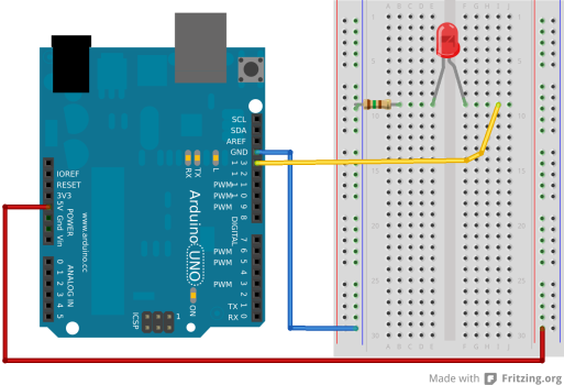
- Remove the wire joining the LED's positive leg to the 5V power rail.
- Use a wire (colour such as white or yellow) to connect the LED's positive leg to pin 13 on the Arduino.
You should now have a circuit that looks like this:
- Plug the USB cable back in.
If you have a brand new Arduino that hasn't been used before the LED should start to blink. This is because it comes from the factory with this test program already installed.
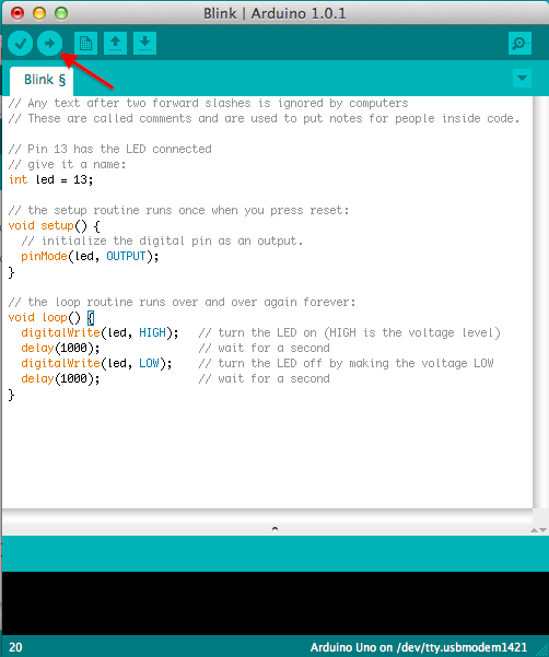
We now write our first program to make it blink. Here's the program code:
// Any text after two forward slashes is ignored by computers
// These are called comments and are used to put notes for people inside code.

// the setup routine runs once when you press the reset button
void setup() {
  // initialize the digital pin 13 as an output, in has the LED connected
  pinMode(13, OUTPUT);
}

// the loop routine runs over and over again forever:
void loop() {
  digitalWrite(13, HIGH);   // turn the LED on (HIGH is the voltage level)
  delay(1000);               // wait for 1000 milliseconds (1 second)
  digitalWrite(13, LOW);    // turn the LED off by making the voltage LOW
  delay(1000);               // wait for a second
}
Copy this code into your Arduino software and upload it.
If all goes well, you should see your LED start to blink! If not, ask for help :)
Here's your first challenge! Try to complete both tasks. This will help you understand the code.
Saying Hello World.
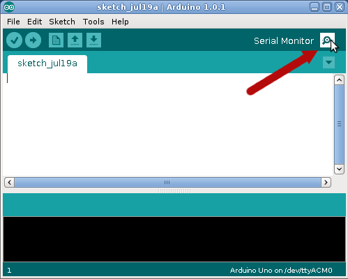
You might already be thinking. How do I know what my program is doing if all the feedback I have is a blinking LED? Well there is a solution in the form of serial communication which allows your Arduino to send messages to a computer. These messages can then be shown on your screen by clicking the button at the top right of the Arduino software.
Note: when handling textual information in the Arduino programming language you need to use double quote marks. In this programming language “digitalWrite” represents text (d followed by an i, followed by a g, and so on, spelling the word digitalWrite), whereas digitalWrite (without the double quotes) is a reference to a feature of the programming language which allows you to control the voltage on various pins.
void setup() {
  // initialize the digital pin 13 as an output, in has the LED connected
  pinMode(13, OUTPUT);

  // initialize serial communication at a speed of 9600 bits per second:
  Serial.begin(9600);
  // Sends a line to the computer
  Serial.println("Hello World!");
}

// the loop routine runs over and over again forever:
void loop() {
  Serial.println("LED On");
  digitalWrite(13, HIGH);   // turn the LED on (HIGH is the voltage level)
  delay(1000);               // wait for 1000 milliseconds (1 second)
  Serial.println("LED Off");
  digitalWrite(13, LOW);    // turn the LED off by making the voltage LOW
  delay(1000);               // wait for a second
}
Once you've uploaded the program, open the Serial monitor:
You should see the Arduino say “Hello World!” followed by LED On and LED Off once a second. If you are having problems, check that the speed in the Serial Monitor is set to 9600. Otherwise, ask a helper!
So that's the end of the 1st lesson.
Once the rest of the group has got to this point there will be another short presentation on programming concepts before moving onto Tutorial 2.
